Battery Ignition system
BATTERY IGNITION SYSTEM :-
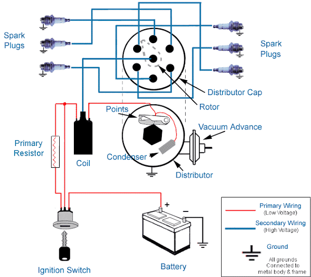
Most of the modern spark-ignition engines use battery ignition sys this system, the energy required for producing spark is obtained from a 6 or 12 volt battery. The construction of a battery ignition system is extremely varied. It depends on the type of ignition energy storage well as on the as ignition performance which is required by the particular engine. The reason for this is that an ignition system is not an autonomous machine, that is, it does not operate completely by itself, but instead it is but one part of the internal combustion engine, the heart of the engine. It is therefore extremely important that the ignition system be matched sufficiently well to its engine.
The main and essential component required for battery ignition system are :-
(1) Battery
(2) Ignition switch
(3) Ballast resistor
(4) Ignition coil
(5) Contact breaker
(6) Capacitor
(7) Distributor
(8) Spark plug
(1) Battery :-
loading...
To provide electrical energy for ignition, a storage battery is used. It is charged by a dynamo driven by the engine. owing to the electro-chemical reactions it is able to convert the chemical energy into electrical energy. The battery must be mechanically strong to withstand the strains to which it is constantly subjected to. Given reasonable care and attention two years or more trouble free life may be obtained from a battery. A lead acid battery consists of a number of cells connected together in series and each having a nominal potential of 2 volts when fully charged. A six volt battery has three such cells and a 12 volt battery has six. six cells are coupled together to form a 12 volt battery and shows that this coupling in series the positive of one cell is connected to the negative of the next.
Two types of batteries are used for spark-ignition engines, the lead acid battery and the alkaline battery. The former is used in light duty commercial vehicles and the later on heavy duty commercial vehicles.
(2) ignition Switch :-
Battery is connected to the primary winding of the ignition coil through an ignition switch and ballast resistor. With the help of the ignition switch the ignition system can be turned on or off.
(3) Ballast Resistor :-
A ballast resistor is provided in series with the primary winding to regulate the primary current. The object of this is to prevent injury to the spark coil by overheating if the engine should be operated for time at low speed, or should be stalled with the breaker in clased position. This coil is of iron ire, and iron has the property that its electrical resistance increases very rapidly if a certain temperature is exceeded. The coil is therefore made of wire of such size that primary current flows nearly continuously, the ballast coil reaches a temperature above that where this rapid increase in resistance occurs. This additional resistance in the primary circuit holds the primary current down to a safe value. For starting from cold this resistor is by-passed to allow more current to flow in the primary circuit.
(4) Ignition Coil :-
loading...
Ignition coil is the source of ignition energy in the conventional ignition sys- tem. This coil stores the energy in its nagnetic field and delivers it at the appropriate time in the form of a ignition pulse through the high-tension tion cables to the respective spark plug. The purpose of the ignition coil is to step up the 6 or 12 volts of the battery to a high voltage, sufficient to induce nn electric spark across the electrodes of the spark plug. The ignition coil consists of a magnetic core of soft iron wire or sheet and two insulated con- ducting coils, called primary and the secondary windings. The secondary coil consists of about 21,000 turns of 38-10 gauge enameled copper wire sufficiently tnsulated to withstand the high voltage. It is wound close to the core with one end connected to the secondary terminal and the other end grounded either to the metal case or the primary coil. The primary winding, located outside the secondary coil is generally formed of 200-300 turns of 20 gaugo wire to produce a resistance of about 1.15ohms. The ends are connected to exterior terminals. More heat is generated in the primary uman in the secondary and with the primary col wound over the sec- ondary coil, it is easier to dissipate the heat. The entire unit whenessembled, is enclosed in a metal container and forms a neat and compact unit. On the top of the coil assembly is the heavily insulated terminal block, which sup ports three terminals To the two smaller terminals , usually marked Sw (switch wire) and CB (contact breaker) the two ends of the primary connected.(5) Spark Plug :-
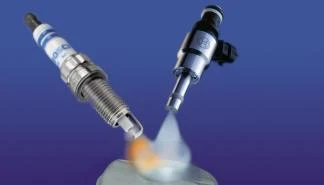
The spark plug provides the two electrodes with a proper gap across which the high potential discharges to generate a spark and ignite the combustible mixture within the combustion chamber. A spark plug consists essentially of a steel shell, an insulator and two electrodes. The central electrode to which the high tension supply from the ignition coil is connected, is well insulated with porcelain or other ceramic materials. The other electrode is welded to the steel shell of the plug and thereby is automatically grounded when the plug installed on the cylinder head of the engine. The electrodes are usually made high nickel alloy to of withstand the severe erosion and corrosion to which they are subjected in use. The tips of the central electrode and the insulator are exposed to the combustion gases. This results in the insulators having a tendency to crack from the high thermal and mechanical stresses. Some insulators are also seriously affected by moisture and by abnormal surface deposits. Since, the central electrode and the insulator are subjected to the high temperature of the combustion gases, the heat must flow from the insulator to the steel shell which is in contact with the relatively cool cylinder head in order to cool the electrodes and thereby prevent preignition.


0 Comments